Major External PIM Issues in Small Cell 5G Systems
The majority of voice and the data traffic on the cellular networks happens in buildings. Depending on the type of building, there can be a high density of the users at any given time, requiring some buildings to need significantly higher cellular capacity requirements than others.
Other factors that affect capacity requirements are LEEDs, green building initiatives (i.e., low-e glass windows), shadowing caused by nearby structures, refractive or advanced material, and other dense materials typically located in the basement or the parking lot. The collection of these factors results in poor cellular coverage for the in-building scenario when receiving signals from outdoor systems. Industries therefore looking for a proper in-building solution to meet the capacity for effective voice and data services for the in-building scenario.
Here is a summary of the current in-building solutions.
Major In-Building Systems
The Distributed Antenna System (DAS) Solution
DAS comes in two different forms: Passive and Active. Passive DAS is very traditional and has been in the market for many years. It involves the use of passive components such as coaxial cables, splitters, and diplexers to distribute an RF signal. Active DAS involves the use of components that require a power source to operate, which is done by connecting remote nodes with fiber optic cables.
Passive DAS
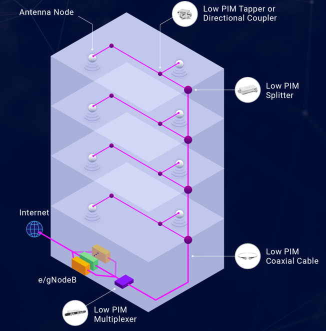
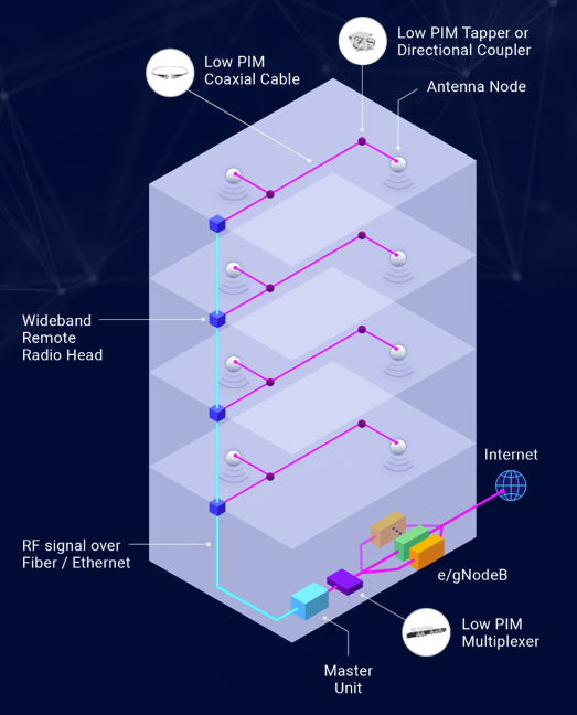
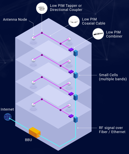
Passive DAS starts with the carriers’ RF signal being transmitted into the building through e/NodeB. A low PIM combiner or low PIM multiplexer will then combine multiple carrier RF signals or multiple band signals and transmit it through the RF coaxial cable to each floor. Low PIM splitters, directional couplers, or tappers then split the RF signal and send them to each antenna node.
Advantages
-
Less Signal Interference. Since the signal is distributed to each antenna from a single combined source, the power level being provided to each antenna node is very low (15-20 dB maximum). This low amount power directed to each node will result in less signal interference overall.
-
Scalable. DAS in general is a scalable network that can meet future capacity requirements and additional carriers by adding additional nodes.
-
Low Maintenance. Since most of these components and cables are passive parts, you typically don't need to touch them again after deployment. Saving money in the long run.
Disadvantages
-
Deployment Cost. The initial cost for coaxial cables and all the other components is quite steep. The cost for the installation of these components is also a large factor in the cost.
-
Coaxial Cable Transmission Can Limit Effectiveness. Since coaxial cables are used for the passive data system, it will likely introduce significant attenuation or insertion loss for the whole system.
-
Internal PIM Issues. Since all Passive DAS components are PIM sourced, you will run into PIM issues if you do not choose the right PIM reduction for all these components or cables, resulting in serious system performance issues.
Active DAS
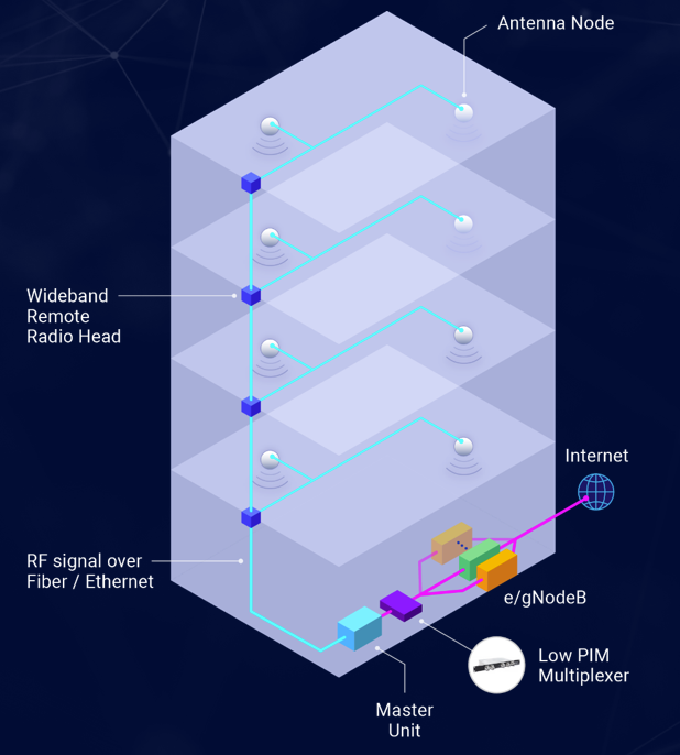
Active DAS is like Passive DAS in many ways, especially at the source. In Active DAS, the carrier brings the signal source, and a multiplexer combines the signals, same as Passive DAS. The system then uses active components: a “master” unit and a “slave” unit. The master unit converts the RF signal into an optical signal, the signal is then transmitted through either optical fiber cable or ethernet cable to the slave unit, which then converts the signal back into RF. The new RF signal is then fed into the antenna nodes to cover the whole building.
Advantages
-
No Internal PIM Issues. Due to ethernet cable and optical cable being used, there are no PIM sources present, so any inter-system PIM issues are no longer present. Although there are still PIM issues, most of it is external PIM.
-
Easy to Deploy. Like Passive DAS, Active DAS does not have many components, making the system is relatively simple.
-
Scalable. DAS in general is a scalable network that can meet future capacity requirements and additional carriers by adding additional nodes.
-
Minimal Insertion Loss: Fiber and/or ethernet cables have no insertion loss (unlike coaxial), enabling the system to operate more efficiently.
-
Low Upfront cost. The cost of optical fiber and/or ethernet cables is significantly lower than coaxial cables.
Disadvantages
- Maintenance Challenges. To maintain Active DAS, you must ensure the active master unit, the many slave units, and the e/gNodeB are operating efficiently. Due to this importance, Active DAS vendors charge a maintenance fee every year. This cost alongside extra issues that many encounter when maintaining such a system, and the possibility of replacing components, results in significant maintenance upkeep.
Small Cell Solution
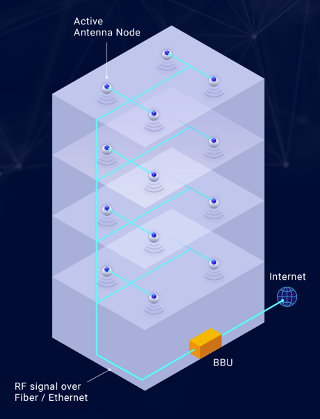
Small cell solutions are more popular in recent years due to the increased usage of small cells (and its ecosystem) in the market for 5G deployments. This method utilizes a baseband unit (BBU) to set the baseband signal through the fiber and/or ethernet cables to each small cell. Each small cell will then irradiate with low power to cover the whole building.
Advantages
-
No Internal PIM Issues. In this system, only the small cell itself might have some internal PIM issues, but the fiber and/or ethernet cables in use won't generate PIM.
-
Easy to Deploy. Like Active DAS, this system is also easy to deploy.
-
Minimal Insertion Loss. Fiber and/or ethernet cables have no insertion loss (unlike coaxial), enabling the system to operate more efficiently.
-
Low Upfront Cost. Since fiber and ethernet cables are easy to deploy, the upfront capital cost is quite low. This is a big reason why many prefer this kind of solution for 5G in-building systems.
Disadvantages
-
Maintenance Challenges. Because the system is entirely composed of active parts, over time they will need to be replaced.
-
No Wideband Solution. Although one single small cell can cover all the bands, especially 5G, bands such as CBRS and LLA bands are not covered.
-
External PIM Issues. The nature of the small cells and their deployment can cause major external PIM issues (PIM generates outside the in-building system). In some cases, this external PIM can be very serious.
Hybrid Solution
This method combines the methods discussed above. This is due to many buildings already having Passive and/or Active DAS in-place while still wanting to upgrade their in-building solution. There are two different kinds of hybrid solutions. One is “Hybrid Active DAS” which is the combination of active and the Passive DAS, and the other is called “Small Cell Hybrid” which is the combination of the small cell solution and the Passive DAS.
Hybrid Active DAS
This system is the most practical upgrade for buildings that already have Passive DAS system installed. Active DAS components such as the master unit and fiber cables will distribute the signal to each floor and the Passive DAS components will carry the 'last mile' signal to the antenna node.
Advantages
-
Best of Both DAS. This method places the Passive and Active DAS components where they will perform best for an in-building scenario, so the building will experience the primary strengths of both methods (i.e., less internal PIM issues, less signal interference, minimal insertion loss).
-
Easy to Upgrade. Does not require an entire overhaul of your current in-building system while still achieving high effectiveness.
Disadvantages
-
Deployment Cost. The Passive DAS components in the system will still cause the cost of deployment to be higher.
-
Maintenance Challenges. With an Active DAS is in place, maintenance costs will increase.
Major External PIM Issues in Small Cell 5G Systems
Let’s suppose we have three small cells; each small cell is a large source of PIM due to their magnetic material contained inside. Upon detection of additional signal from another small cell, it would generate a PIM product which then radiates over the air to the receiving band at the source small cell. This will result in a polluted signal which will impact the performance of the small cell system.
PIM research results show that a strong signal combined with a weak signal can generate a serious PIM issue. For instance, let's assume 'cell C' transmits a signal over the air directly to 'cell A'. The signal will be heavily attenuated, caused by the air medium or signal reflection from a neighbouring cell B, which results in a weak signal received at cell A. Because cell A already produces a strong radius signal, cell A's antenna will receive a combined strong and weak signal, resulting in an extreme PIM issue at the receiving band. This was addressed in a research paper published on IEEE's paper, “Empirical Equation for Carrier Power Dependence of Passive Intermodulation Product.”
Here is a summary of their findings:
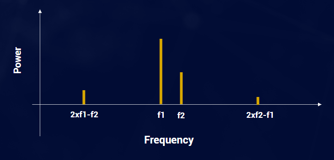
The study had two signals: carrier one and carrier two, which is frequency one f1 and f2 respectively. The third order PIM production is (2f1)-f2 and (2f2)-f1. The research results show the third order PIM level at (2*f1)-f2 is a major concern because it is localized in the lower side when it's supposed to be on the receiving band side. The third order PIM, f1, will have a major pim level impact. Even if f2 drops lower in comparison to f1, the PIM products are still very much present. Most believe that two frequencies of equal power will result in the worst PIM impact. These results now prove that theory false: If f1 is instead very high and f2 very low, especially when f1 is twice the power of f2, the PIM product can be massive.
Test Case 1
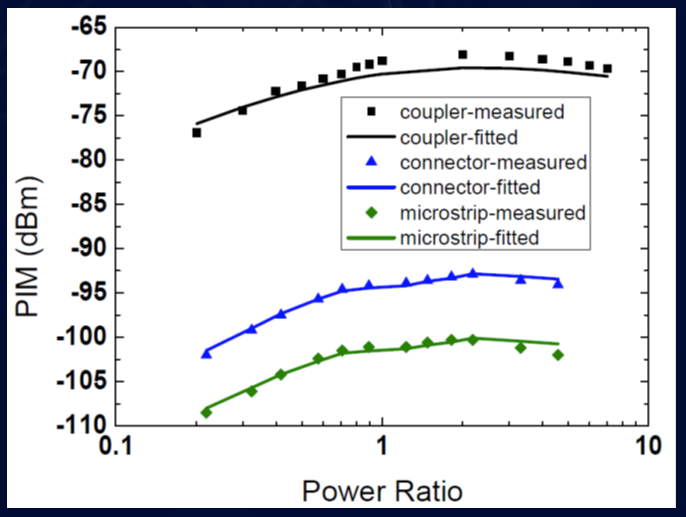
For this test case researchers applied a total power of 40 watts to frequencies f1 (primary frequency) and f2 (external frequency). They used three different components to run the test to measure the PIM. The black line represents a coupler, the blue line represents an adapter, and the green line represents a microstrip. The researchers then adjusted the power ratio between f2 and f1 and measured the third order PIM. The results found are displayed on the graph below, with the Power Ratio being f1/f2 and equation for PIM being (2*f1)-f2.
As shown in the graph, the PIM levels only increase as f1 gains a higher distribution of power. The lowest PIM occurred when f2 was much higher than f1, and the highest PIM occurred when f1 was approximately twice the power of f2. The graph also demonstrates how a power ratio of 1 (equal power from both frequencies) is not the worst-case PIM scenario. When taking these results into consideration, it only makes the task of deploying multiple smart cells in the field more challenging. If the cells too close to one another, the aversive combination of a strong and weak signal is possible. If the cells are too far apart, the cost for components will increase.
Test Case 2
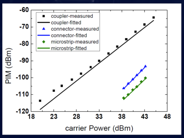
Another interesting analysis they conducted was applying equal power for f1 and f2, then increasing their power simultaneously. (see graph)
For the coupler, the PIM increases in increments of approximately 2 db when carrier power increases by 1 db. For the other two components the increments are instead between 2 to 2.6.
Solutions
The first solution could be physically moving the antennas further away from one another. This requires the addition of extra fiber and/or ethernet cables, which will increase deployment costs. The second solution involves a Hybrid Smart Cell System, which 'moves' or 'transfers' external PIM to a controllable internal PIM impact, which can be far easier to reduce, and can be managed by high PIM rejection components.
Hybrid Small Cell Solution
Multi carrier and multi-band small cells will distribute the signals to each floors, and the cells will connect to a high PIM reduction combiner. After that, Passive DAS with controlled PIM components will use passive DAS antennas. The system's RF signals share a single pathway to the antenna so external PIM issues will not be generated.
Advantages
-
Minimal PIM Issues. External PIM is negated by the external signals being combined into internal signals. The internal PIM is then handled using low PIM components.
-
Minimal Insertion Loss. All long-distance cabling is fiber and/or ethernet, while the coaxial cabling is limited to short distances. This allows insertion loss to be kept at a minimum.
-
Easy to Upgrade. To add another band to your network, simply add another small cell and extend the port of your combiner. By combining the signal they will now share the same Passive DAS.
Disadvantages
- Deployment Cost. The cost of deployment may be a little bit higher because still there is Passive DAS involved.
Note: a lot of buildings are already covered by Passive DAS, especially on a floor-to-floor basis. If that is the scenario, then the system would be much easier to deploy because it would only require a swap of the existing system that distributes the signal from the source to each floor. Since Passive DAS components are already present on each floor, they will not need to be replaced.
For your in-building system, we recommend using Radiocomm’s high PIM reduction components to prevent these PIM issues from occurring. All our components are -165dBc and are used by many large venders to deploy and maintain 3g, 4g, and 5g networks in all scenarios.
To learn more about DAS and Hybrid DAS, you can read our Guide to 5G: Distributed Antenna Systems.
Interested in learning how Radiocomm's products and solutions can help your projects? Browse our e-catalogue or contact us directly for customized, expert solutions.
About Radiocomm
Acentury is a proven technology and software company in the wireless communications industry. For over ten years we have designed and deployed solutions, products, and services for Tier 1 carrier operators and internet-scale enterprises across the Americas. With our Radiocomm product brand, we feature industry-leading extra low PIM (-165dBc) components and cables for 5G wideband outdoor and in-building DAS applications. We have successfully deployed thousands of network components that meet the requirements and scale of several carrier-grade networks with zero field returns to date. Our fiber optic product portfolio is comprehensive and features highly durable properties for all applications and integrated solutions.
Radiocomm continues to maintain a reputation for superior performance with outstanding reliability and quality; we stand by our passive network components with a 1yr manufacturing warranty along with a test record printout for each component we ship.
Reference(s):
- Ming Ye, Yong-ning He and Hui Zhu, "Empirical equation for carrier power dependence of passive intermodulation product," 2015 IEEE International Wireless Symposium (IWS 2015), 2015, pp. 1-4, doi: 10.1109/IEEE-IWS.2015.7164600.
Have a question or comment?
We'd love to hear it. Fill out our General Inquiry Form or reach us directly at: info@acentury.co
CONTACT US